The working precept of the enzyme sensor
As proven in Scheme 1, the FG OECT has two key parts: a sign amplification unit (AU) and a sensing unit (SU). The AU consists of a supply (S), a drain (D), a semiconducting channel, a main floating gate (FG1), and a main electrolyte, whereas the SU consists of a secondary floating gate (FG2), a management gate (CG), and a secondary electrolyte. The secondary electrolyte gives a response pool for the SU, whereas the interface capacitance of the electrical double layer (EDL) shaped between the first electrolyte and the semiconducting channel serves because the dielectric layer for the AU. The FG construction can separate the gate dielectric electrolyte (main electrolyte) from the biochemical response electrolyte (secondary electrolyte), decouple the sign amplification and biochemical sensing processes, and obtain impartial AU and SU construction design and efficiency optimization.
Specifically, the Ag/AgCl electrodes are employed as CG and FG1 concurrently, the poly (3,4-ethylenedioxythiophene)-poly(styrenesulfonate) (PEDOT: PSS) serves because the semiconducting materials, the 100 mM NaCl serves as the first electrolyte, and the secondary electrolyte is the aqueous resolution containing metabolites to be examined. To transform analyte focus right into a voltage sign, we modify FG2 utilizing the stacking construction of BBL-Nafion-enzyme-Nafion. If sweat metabolites, particularly glucose, lactate, and uric acid, exist within the secondary electrolyte, embedded enzymes, such because the Gox, may catalyze glucose and produce H2O2. Then, the BBL movie catalyzes the H2O2 and induces an electrochemical Nernst potential (Formulation 1), which is able to additional management FG1’s electrical potential:
$$:{E}_{textual content{Nernst}}={E}^{textual content{0}}+frac{{kT}}{{ne}}textual content{ln(}frac{textual content{[OX]}}{textual content{[Red]}}textual content{)}$$
(1)
the place [Ox] and [Red] are oxidized and lowered species concentrations, respectively, E0 is the formal potential, okay is Boltzmann’s fixed, T is the temperature, e is the elemental cost, and n is the variety of electrons transferred through the response.
FG OECT fabrication and delicate layer optimization
Pt electrodes are broadly used within the catalysis of H2O2. Nonetheless, Pt electrodes are incompatible with standard gear, comparable to wire bonders, limiting their utilization in OECT. Thus, most often, the electrodes and leads of OECT are normally primarily based on Au. Alternatively, Prussian blue (PB) might be simply electrodeposited on the floor of gold electrodes and work as a catalyst for H2O2. It’s identified to be ‘‘synthetic peroxidase’’ resulting from its excessive catalytic exercise and selectivity towards H2O2. Nonetheless, making ready PB movie requires extremely poisonous potassium ferrocyanide (Ok3Fe(CN)6). Herein, we used BBL, modifying the Au electrode, because the catalyst for H2O2 to beat these above limitations.
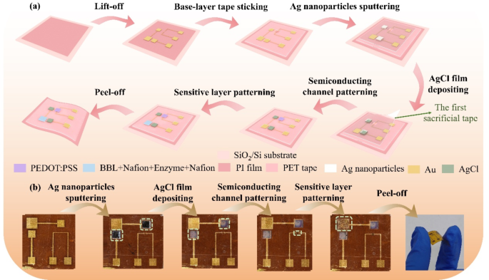
A multi-step patterning course of is used within the present work to understand the FG OECT’s fabrication (Fig. 1a). Step one is to make use of microfabrication know-how to arrange Au microelectrodes on PI (Polyimide) movie with a thickness of seven μm supported by the SiO2/Si substrate (Notice 1 and a pair of, Supporting Data). Within the second step, a polyethylene terephthalate (PET) tape—known as base-layer tape with holes aligned with all of the electrode pads, the hole between the supply and drain electrode, and all of the microelectrodes aside from the supply and drain is patterned by a laser marking machine and connected to the microelectrodes chip, with no peeling in the entire fabrication course of. Within the third step, we put together one other PET tape—the primary sacrificial tape—with holes aligned with the FG1 and CG electrodes and fasten it to the base-layer tape. The Ag nanoparticles are sputtered onto FG1 and CG utilizing a magnetron sputterer and soaked in 10− 1 M FeCl3 resolution to deposit Ag/AgCl movies [21, 22]. After eradicating the primary sacrificial tape, non-polarized Ag/AgCl electrodes are shaped on the FG1 and CG. Within the fourth step, the third piece of perforated tape, named the second sacrificial tape (not proven), is used to realize a patterned semiconducting layer. The second sacrificial tape presents a gap aligning with the source-drain electrode hole, during which the PEDOT: PSS combination (Notice 3, Supporting Data) shall be spin-coated. A semiconducting channel may very well be obtained after peeling off the second sacrificial tape. Within the closing step, we use a 3rd sacrificial tape (not proven) to sample the stacked delicate layer—BBL-Nafion-enzyme-Nafion, whose preparation process shall be mentioned subsequent. Determine 1b reveals the optical picture of the ready FG OECT.
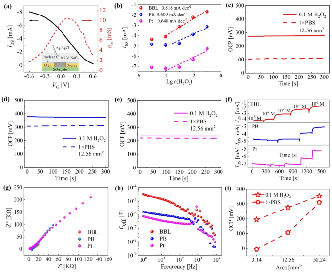
Optimization of the delicate supplies to catalyze hydrogen peroxide (H2O2). (a) Schematic diagram of the standard OECT construction to calibrate the semiconducting channel’s efficiency and the obtained switch and transconductance curves. (b) Calibrating the detection sensitivity of H2O2 when utilizing Pt, poly(benzimidazobenzophenanthroline) (BBL), and Prussian blue (PB) because the delicate supplies, respectively. The open circuit potential (OCP) is obtained in PBS and 10− 1 M H2O2 by (c) BBL-modified Au electrode, (d) PB-modified Au electrode, and (e) Pt electrode. (f) The semiconducting channel present (IDS) versus time diagram is obtained beneath completely different concentrations of H2O2 at VCG = 0 V. (g) Electrochemical impedance spectroscopy (EIS) investigation outcomes. (h) The equal capacitances. (i) OCPs for BBL-modified Au electrodes in numerous areas
Primarily based on the fabrication course of, a semiconducting channel presenting a size of 20 μm, a width of 10 μm, and a peak of 0.17 μm may very well be obtained. Utilizing Ag/AgCl electrodes because the gate electrode, the switch and transconductance curves of OECT utilizing the standard three-electrode construction (Fig. 2a) at drain bias (VD) of -0.60 V are investigated, presenting a peak transconductance as much as 10.32 mS. When investigating FG OECT’s response, the management gate bias (VCG) is about at 0 V to completely make the most of the electrochemical potential produced within the SU to manage the AU, in accordance with Siew’s current work [23]. For the reason that non-polarizable Ag/AgCl electrodes function each FG1 and CG, the Nernst potential generated by the cascade reactions within the SU shall be transmitted to the AU to manage the IDS. Thus, the extra vital the electrochemical potential that may be generated in H2O2 catalysis, the extra pronounced the present response of FG OECT. We use FG2 of the identical space for straightforward comparability, stored persistently at 12.56 mm2, which equals the 4 mm diameter industrial Pt electrode space. BBL and PB movie must be deposited on the substrate. Herein, gold sheets with a 12.56 mm2 uncovered patterned space are employed because the substrate, and the manufacturing parameters are tuned to match the thickness of the BBL and PB movies (Notice 4, Supporting Data).
Determine 2b signifies that BBL has the very best sensitivity for H2O2 detection within the FG OECT configuration, per the open circuit potential (OCP) investigation outcomes (Fig. 2c and e). Intimately, the OCPs are obtained in PBS and 10− 1 M H2O2 utilizing working electrodes of various supplies whereas protecting the Ag/AgCl electrode because the reference and counter electrodes. The experimental outcomes present that BBL reveals the utmost OCP distinction (168.16 mV), and thus, the corresponding fluctuation amplitude of IDS is the biggest when the H2O2 focus will increase from 10− 5 M to 10− 1 M (Fig. 2f). Notice in Fig. 2f that the output present of the OECT obtained in H2O2 is completely different. We carried out electrochemical impedance spectra (EIS) investigations of varied electrodes (Fig. 2g) in 10− 1 M H2O2 to elucidate the phenomenon. The experimental outcomes present that, at low-frequency excitation (10− 1 Hz), the BBL-modified Au electrode has probably the most vital equal capacitance (3.21 × 10− 5 F), whereas the Pt electrode presents probably the most negligible equal capacitance (7.55 × 10− 7 F) (Fig. 2h), which was estimated from the Nyquist plot utilizing the out-of-phase impedance (Z″=1/2πfCeff) [24]. In line with the precept of collection circuits (Notice 5, Supporting Data), the semiconducting layer will undertake the utmost voltage division and produce the minimal output present when the BBL-modified Au electrode is used. As well as, we discover that whatever the electrode kind, absolutely the worth of IDS decreases with the rise of H2O2 focus in Fig. 2f. The reason being that when H2O2 is added dropwise within the SU, the Nernst potential generated by the electrochemical response will increase with the increment of H2O2 focus (Formulation 1), leading to an rising efficient FG voltage (VFGeff) and eventually resulting in a decrement of the output present of OECT [25].
Primarily based on the electrode materials optimization, we subsequently investigated the impact of the FG2 electrode geometry on the H2O2 catalysis. The BBL movie was stored at a thickness of 175 nm with a spin-coating pace of 2000 rpm (Notice 4 within the Supporting Data). The substrate areas fluctuate from 3.14 mm2 to 50.24 mm2. As depicted in Fig. 2i, the OCP distinction of BBL-covered Au electrodes in PBS and 10− 1 M H2O2 decreases with the rise of electrode space, per our earlier work concerning H2O2 sensors utilizing Pt electrode as FG2 [14]. Furthermore, the gate bias comparable to the height transconductance is 100 mV (Fig. 2a), falling nicely inside the scope of electrochemical potentials (between − 5.00 and 194.61 mV) generated by the BBL-modified Au electrode of three.14 mm2 space in PBS and 10− 1 M H2O2 (Fig. 2i). Subsequently, within the following sensor investigations, we’ll use a gold sheet with an space of three.14 mm2 and modify it with the BBL-Nafion-enzyme-Nafion stacked layer because the FG2 for developing FG OECT-based enzyme sensors.
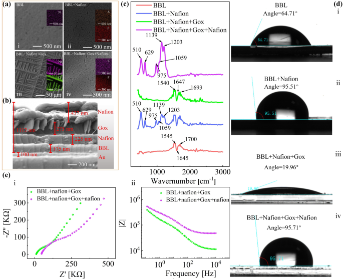
Characterizations of the stacked layer. (a) The scanning electron microscope (SEM) picture of (i) BBL layer deposited on the Au substrate, (ii) backside Nafion layer, (iii) glucose oxidase (GOx) layer, (iv) higher Nafion layer, (b) The cross-sectional view SEM. (c) Fourier transforms infrared (FT-IR) spectra of every layer. (d) The wettability characterizations of (i) BBL movie, (ii) BBL-Nafion stacked layer, (iii) BBL-Nafion-Gox stacked layer and (iv) BBL-Nafion-GOx-Nafion stacked layer, (e) The EIS characterizations of the BBL-Nafion-GOx and BBL-Nafion-GOx-Nafion stacked layers, (i) the Nyquist plot, (ii) the Bode plot
We then assemble completely different stacked FG2 buildings primarily based on the optimized parameters for detecting glucose, lactate, and uric acid. First, the BBL is ready by electrodeposition following the methodology described in Notice 4 within the Supporting Data. Afterward, the preparation of the stacked Nafion-enzyme-Nafion layer is predicated on the strategies described within the literature [26, 27]. In short, a primary layer of Nafion is fabricated by drop casting 10 µL of the Nafion resolution onto the as-prepared BBL movie and air-dried in a single day at room temperature. The enzymatic layer is ready by drop casting 10 µL of an answer containing 20 mg·mL− 1 of enzyme in distilled water onto the primary Nafion layer. Afterward, the stacked layer is left to dry for six h at 4 ℃. Lastly, one other 10 µL of the Nafion resolution is utilized to make the higher layer that entraps the enzymatic layer and let dry in a single day at room temperature. The stacked FG2 electrodes are stored at 4 ℃ when not in use.
The scanning electron microscope (SEM) characterizes the electrode morphology through the layer-by-layer modification. Herein, GOx remains to be employed for instance for the demonstration. As proven in Fig. 3a-i and a-ii, the Nafion layer is efficiently deposited on the BBL movie. Afterward, new dendritic patterns are generated by the bodily adsorption of GOx (Fig. 3a-iii). Lastly, the highest Nafion layer is deposited (Fig. 3a-iv), forming the same sample to Fig. 3a-ii. Centered-ion beam scanning electron microscopy (FIB-SEM) is used to confirm stacked FG2 buildings on the nanoscale (Fig. 3b). Stacking completely different layers (BBL, backside Nafion, GOx, and prime Nafion layers) is distinguishable from the picture. From FIB-SEM analyses, the thickness of the BBL layer, backside Nafion layer, GOx layer, and prime Nafion layer are discovered to be about 175 nm, 225 nm, 275 nm, and 437 nm, individually.
We have now employed the Fourier transforms infrared (FT-IR) spectrometry to confirm the composition of every layer. As proven in Fig. 3c, the fingerprint band at 1700 cm− 1 is attributed to the C = O vibration, the band at 1645 cm− 1 is attributed to destructive polarons in BBL, whereas the 1545 cm− 1 band is attributed to the C = C vibration [28]. Then, the Nafion layer is spin coated, the place the band at 629 cm− 1 is assigned to the stretching C-S teams; the band at 975 cm− 1 is assigned to C-O-C stretching [29]; the band at 1203 cm− 1 is assigned to the uneven C − F stretching vibrational modes [30]. Subsequently, the GOx protecting the underside Nafion layer is spin-coated, and the FTIR outcomes current obvious contributions of amide I (at 1647 and 1693 cm− 1) and amide II (at 1540 cm− 1) [31].
Determine 3d reveals the adjustments in wettability through the preparation strategy of the stacked layer. The BBL is hydrophilic with a contact angle of 64.71° when utilizing deionized ultrafiltered water because the testing liquid. Nonetheless, the contact angle barely will increase when the BBL movie is roofed with Nafion membranes as a result of inherent hydrophobic properties of Nafion [32, 33]. Nonetheless, after dropping forged GOx onto the underside Nafion layer, the contact angle of the stacked construction is considerably lowered to 19.96° as a result of hydrophilicity of GOx. Stacking the higher Nafion layer restores the contact angle to 95.71°, similar to Fig. 3d-ii. Determine 3e reveals the corresponding EIS investigation ends in the final two steps, carried out in 1 mM glucose resolution. When the higher Nafion layer covers the GOx layer, the slope of the Nyquist plot decreases from 1.18 to 0.90, indicating that protecting the higher Nafion layer is much less conducive to move the analyte resolution [34], per the wettability investigation consequence. It is also verified by the Bode plot, the place the electrode impedance barely will increase at low frequencies when the higher Nafion layer covers the GOx layer.
Responses of FG OECTs to typical analytes
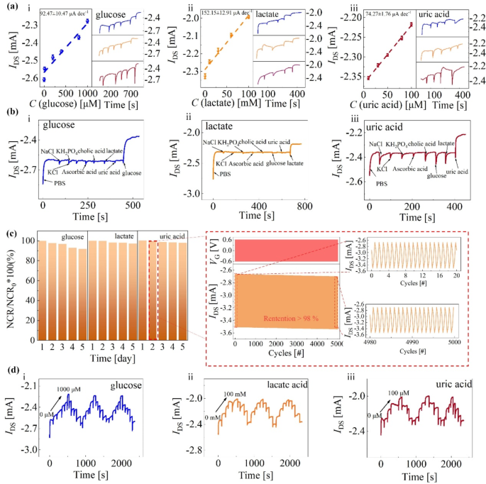
Lastly, we assemble the as-prepared sensing component of stacked BBL-Nafion-enzyme-Nafion layers, Ag/AgCl electrode, and semiconducting channel to assemble FG OECT (Fig. 1) and put together glucose, lactate, and uric acid sensors utilizing the identical processing method by altering the enzymes varieties within the stacked layer. As proven in Fig. 4a (i-iii), the obtained glucose, lactate, and uric acid detection sensitivities are 92.47, 152.15, and 74.27 µA·dec− 1, respectively. The selectivity of the glucose/lactate/uric acid sensor is verified by the negligible response of non-target metabolites and ionic compositions, which have the identical focus because the substance to be detected (1 mM for i, 100 mM for ii, 100 µM for iii, respectively) (Fig. 4b). As well as, we carried out stability testing on the sensor over 5 days, with 5000 cycles of pulse testing carried out day by day. Intimately, the VG step from − 0.60 to 0.60 V, with a pulse width and responsibility cycle of 0.25 s and 50%, respectively (Fig. 4c). The outputs of glucose, lactate, and uric acid sensors decay by 8.05%, 2.83%, and a pair of.09%, respectively. The soundness testing beneath biking the analyte concentrations has additionally been investigated (Fig. 4d). Herein, the hysteresis width was outlined because the semiconducting channel present (IDS) distinction between the preliminary and closing electrolyte resolution on the similar analyte focus. For glucose detections, the hysteresis width within the 0–1000 µM loop obtained within the third cycle is eighteen.30 µA, about 0.71% of the preliminary IDS (2.58 mA). Primarily based on the glucose detection sensitivity (92.47 µA·dec− 1), this hysteresis width solely introduces a deviation of about 0.20 dec glucose. For the lactate acid, the hysteresis width obtained within the three cycles is 1.21%, 2.58%, and 1.02%, respectively. Concerning the uric acid, the hysteresis width obtained within the three cycles is 1.28%, 1.39.%, and a pair of.34%, respectively. It’s price noting that the electrode modified with the BBL layer can rapidly attain an equilibrium state in hydrogen peroxide (Fig. 2f). Nonetheless, if the BBL-Nafion-enzyme-Nafion stacked construction is positioned within the analyte aqueous resolution, the open circuit potential to succeed in equilibrium will considerably enhance(Fig. 4a). The gradual catalytic charge of enzymes in the direction of analytes and the hindering impact of the Nafion layer on the analyte transport, as indicated by the wettability and EIS investigations ends in Fig. 3, might trigger the systematic drift of IDS independently from the detected metabolites (Notice 6 and Notice 7, Supporting Data).
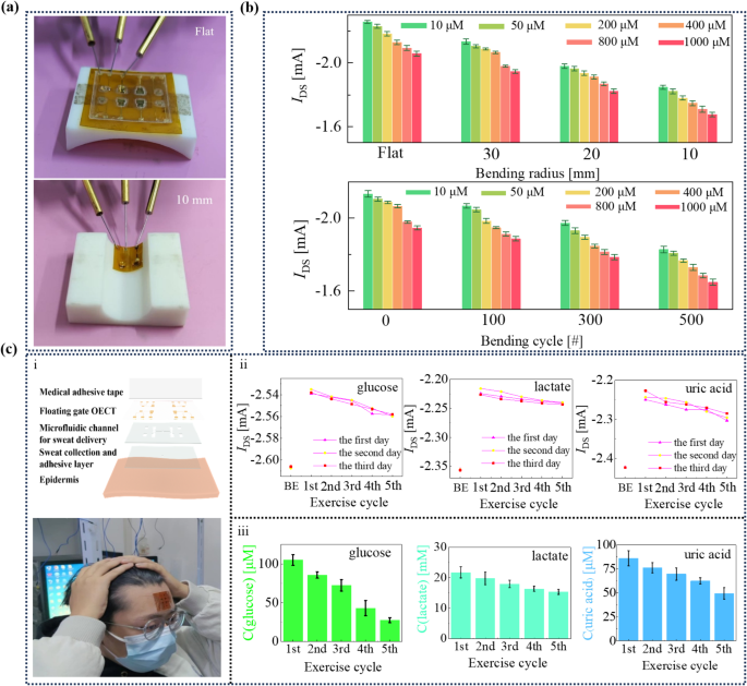
The wearable enzyme sensors. (a) The experimental setup for investigating the wearable enzyme sensor. (b) The retention of versatile sensor present beneath completely different bending situations. (c) The structural schematic (i), the optical {photograph} of wearable enzyme sensors (i), and the investigation outcomes of sweat metabolites on volunteers throughout workouts (ii and iii). In Fig. 5c-ii, BE stands for “earlier than train”. The error bar signifies the usual error of three impartial exams
The present output of the versatile enzyme sensor is electrically characterised beneath completely different bending states with a probe station (Fig. 5b) to guage the sturdiness. Herein, we nonetheless take glucose sensing for instance. The utmost attenuation happens at a bending curvature of 10 mm. For 10, 50, 200, 400, 800, and 1000 μm glucose aqueous resolution, the sensor outputs are − 1.85 ± 0.01, -1.82 ± 0.02, -1.78 ± 0.01, -1.75 ± 0.02, -1.71 ± 0.02, and − 1.68 ± 0.01 mA. In comparison with the flat state, the attenuation is eighteen.10%, 18.25%, 18.41%, 17.91%, 18.33%, and 18.58%, respectively. As well as, after 500 bending cycles, at R = 30 mm, the attenuation is 14.31%, 14.12%, 15.33%, 16.24%, 14.82%, and 15.31% for 10, 50, 200, 400, 800, and 1000 μm glucose detections, respectively. Since completely different enzymes may very well be mounted on the SUs of FG OECT, every particular enzyme will catalyze the sweat metabolites, producing the Nernst potential that drives the FG OECTs. Subsequently, quantitative evaluation of sweat metabolites, together with glucose, lactate, and uric acid, may very well be achieved on this FG OECT-based enzyme sensor.
The wearable enzyme sensor consists of 4 layers: (i) a skin-compatible adhesive layer with an inlet opening for sweat assortment, (ii) a microfluidic channel for sweat supply, (iii) an enzyme-based FG OECT for sweat metabolite sensing (Fig. 5c), which shall be connected on the volunteer’s brow, and (iv) A medical-grade adhesive layer is used to allow the sturdy and seamless adhesion of the wearable enzyme sensor on the brow [35]. The inlet opening (2 mm in diameter) improves entry to the sweat glands and maximizes the sweat assortment [36]. The microfluidic machine is comprised of a double-sided adhesive layer (thickness, 200 μm) with 4 channels (width, 1 mm) for sweat supply. The laser engraving generates the patterns on the adhesive layers.
We have now carried out 3 times of on-skin validation experiments on the identical volunteer over three days. As a result of wired connections required between our chip and the source-measure unit, the volunteer must pause the train after sweating. Thus, on every day, the volunteer wants to interact in a five-cycle jogging train and every cycle ends with visible sweating on the brow. After every train cycle, the metabolites are detected sequentially after connecting the sensor with the source-measure unit. Throughout the measurements, a 30-second take a look at is carried out for every analyte to acquire a secure present response, and every measurement cycle takes roughly 2 min. The primary present worth in Fig. 5(c) is recorded earlier than the train, indicating the semiconducting channel present obtained beneath solely the motion of the drain bias, whereas with out the impression of sweat. As proven in Fig. 5(c), the alerts of glucose, lactate, and uric acid attain their peak through the first train cycle, indicating that the volunteer undertakes the very best coaching depth through the first train cycle. Because the train progresses, the volunteer subconsciously reduces the depth of the coaching. Primarily based on the adjustments in present values recorded, the glucose, lactate, and uric acid focus adjustments throughout consecutive measurements are roughly 77.41 µM, 6.41 mM, and 36.63 µM, respectively. Each the development and the variation in metabolite focus are per literature reviews [37,38,39,40,41]. The consequence means that the wearable enzyme sensor may gather sweat from the pores and skin and independently detect the metabolites secreted by the sweat glands in SUs of the FG OECT. All the experimental course of is recorded within the connected film (Suppmentary film 1). The limitation of the present gadgets is the wired reference to the exterior readout gadgets. Wi-fi sign switch represents a chance for distant information assortment.


